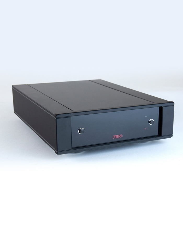
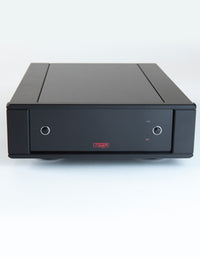
Rega Aria MK. 3 Amplifier
In stock
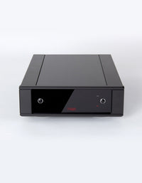
Housed within a brand-new, highly rigid half-width case, the Aria Mk.3 features two entirely separate, high-performance phono stages compatible with both Moving Coil and Moving Magnet cartridges.
Note: All Aria MK3 MC settings will be factory preset for all Rega MC cartridge models. See Specifications for more information.
The Aria is an ""all analogue amplifier"" with no digital control circuitry. The fully aluminum case screens the internal circuit from any stray RFI signals. Our designers have avoided including any superfluous gadgets as they obstruct the signal path and degrade the sound quality. The Aria incorporates many innovative design ideas including a self-adjusting servo control to keep the MC input circuit at its optimum, compensating for any variations in ambient or operating temperature.
Both stages have their own separate input sockets and input pre-amplifier circuitry. This enabled us to design bespoke input circuitry for each cartridge type without compromise. Signal switching is performed at high level and low impedance (via relays) ensuring there is no degradation of the signal.
MC Stage Design & Features
The MC input uses parallel connected, low noise FET's (Field Effect Transistor's) configured as a compound pair. The use of FET transistors ensures there is no bias current flowing in the cartridge coil so as not to upset the delicate magnetic geometry of the cartridge. The MC input has the provision for selecting resistive input loading of 70ohms to 400ohms and capacitive loading of 1000pF to 4200pF. The input sensitivity can be changed by 6dB via the back panel.
MM Stage design & features
The MM input uses low noise, bipolar input transistors also configured as a compound pair. There are two separate power supplies for each channel and further sub-power supplies for each of the low noise input circuits. Nichicon FG electrolytic capacitors have been used in critical positions throughout the power supplies. Polypropylene capacitors have been used in the signal path and equalization networks. Discrete circuitry is used throughout the signal path ensuring full control of the circuit design.
Maximum output level = 11v RMS
Rated output level = 200mV
Output resistance = 100Ù
Minimum output resistance for a –3dB point at 15Hz = 1K
AC supply 230v & 115v Nominal +/- 10%
230v 20mm Fuse T250mAL
115v 20mm Fuse T500mAL
Power Consumption = 10 Watts
Ambient operating temperature 5 to 35°C
Dimensions: W 218mm x D 315mm (325 incl earth nut) x H 78mm


